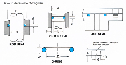
O-Ring Groove Design

| Diametral Squeeze (Minimum) |
Gland Depth | Groove Width +/-.003 |
Diametral Clearance (Maximum) |
|||||||||
| Uniform Dash Number |
Actual Cross Section Diameter |
Dynamic1 | Static | Dynamic1 +.000 -.001 |
Static +.000 -.004 |
No Backup Ring |
One Backup Ring |
Two Backup Rings |
500 PSI | 1500 PSI | Eccentricity (Maximum) |
Radius |
| F | G | D | R | |||||||||
| -.001 | .040 +.003 | .004 | .006 | .033 | .031 | .056 | - | - | .005 | .0025 | .002 | .010 |
| -.002 | .050 +.003 | .005 | .008 | .042 | .039 | .070 | - | - | .006 | .003 | .002 | .010 |
| -.003 | .060 +.003 | .009 | .009 | .051 | .048 | .084 | - | - | .007 | .0035 | .002 | .016 |
| -.004 thru -.050 | .070 +.003 | .007 | .011 | .060 | .056 | .098 | .140 | .207 | .008 | .004 | .002 | .016 |
| -.102 thru -.178 | .103 +.003 | .010 | .015 | .090 | .085 | .144 | .173 | .240 | .009 | .004 | .002 | .016 |
| -.201 thru -.284 | .139 +.004 | .014 | .021 | .121 | .114 | .195 | .210 | .277 | .010 | .006 | .003 | .031 |
| -.309 thru -.395 | .210 +.005 | .021 | .032 | .184 | .173 | .294 | .313 | .412 | .011 | .007 | .004 | .031 |
| -.425 thru -.475 | .275 +.006 | .028 | .042 | .241 | .227 | .385 | .410 | .540 | .012 | .008 | .005 | .047 |
Note 1. The following sizes are not normally recommended for dynamic service:
[ -001 thru -003 ] [ -013 thru -050 ] [ -117 thru -118 ] [ -223 thru -284 ] [ 350 thru -395 ] [ -164 thru -475 ]
Note 2. Clearances shown are based on 70 durometer values.
Note 3. TIR between groove and adjacent bearing surface. Surfaces and corners must be free of tool marks and scratches.
Example Calculations to Determine O-Ring Groove Dimensions:
Rod Seal Example
Given:
Rod Diameter C = .500
O-ring Cross Section W = 3/32 nominal
Dynamic application
No back-ups required
Determine:
O-ring size = AS-568-112 (1/2 ID x 3/32 W nominal dimensions)
Gland depth F = .090 +.000 -.001 (from chart)
Groove width G = .144 +/-.003 (from chart)
Rod Gland D = C + 2F = .500 + 2 x .090 = .680
Piston Seal Example
Given:
Cylinder Bore A = 1.000
O-ring Cross Section W = 1/8 nominal
Static application
No back-ups required
Determine:
O-ring size = AS-568-210 (1 OD x 1/8 W nominal dimensions)
Gland depth F = .114 + .000 - .004 (from chart)
Groove width G = .195 +/-.003 (from chart)
Rod Gland D = A - 2F = 1.000 -2 x .114 = .772
contact us
Ponn Machine Cutting Co., Inc.
20A Cross Street
Woburn MA, 01801
Call Us: (781) 937-3373
Fax: (781) 937-0372
Email: sales@ponnmachine.com


